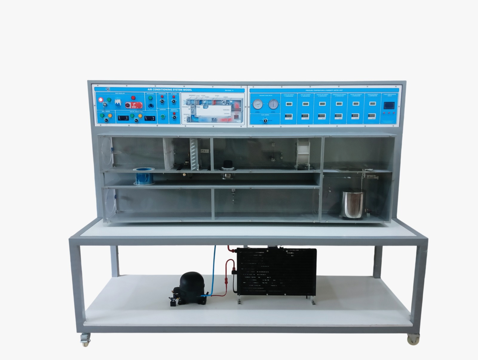
01. SYSTEM OVERVIEW The SB-HVAC-11 is a student laboratory air conditioning trainer used to study the fundamentals of air handling, cooling, heating, humidification, and the mixing of outside (fresh) air with recirculated room air. The trainer reproduces, on a laboratory scale, the essential functions of a real air handling unit (AHU) together with a simulated conditioned space (chamber) that can be loaded with sensible and latent heat. The system consists of an air duct with a transparent front panel for observation, a fan, an air cooler (evaporator of a refrigeration circuit), an electric air heater, a steam/electric humidifier, motorized mixing flaps, and a range of temperature and humidity sensors distributed along the airflow path. A separate chamber fitted with adjustable electric heaters simulates the sensible (dry) and latent (wet) cooling load of a conditioned space. The unit is automation-ready, with four data-cable connections for integration with different control solutio
02. CORE HARDWARE SPECIFICATIONS
Refrigerant Type: R134a
Air-Cooled Condensing Unit — Power Consumption: 140 W at ?10 °C evaporating temperature.
Air-Cooled Condensing Unit — Refrigeration Capacity: 320 W at +5/40 °C (evaporating/condensing temperature)
Humidifier — Heating Power: 400 W
Air Heater — Heating Power: 360 W
Chamber Heaters (Sensible + Latent Load) — Power Output: 0…250 W each, freely and independently adjustable
Air Duct — Flow Cross-Section: To be measured/recorded from the duct nameplate on the trainer used
Display & Control Panel: TFT display showing real-time temperature readings for all monitored segments/zones; also provides full on-unit control of the entire process
Remote Monitoring (Web Server): Built-in web server for remote monitoring via browser — live process data, automatic data logging, and temperature trend graphing
03. COMPONENT LEGEND
Model of the Air Conditioning System: Overall unit combining outside-air and recirculating-air operation in a single trainer.
Air Duct with Transparent Front: Allows visual observation of the airflow and the internal components.
Air Duct with Fan, Air Cooler, Humidifier, Flaps, Air Heater and Sensors: Main process duct in which the supply air is conditioned (moved, cooled, dehumidified/humidified and heated) before entering the chamber.
Chamber with Wet (Latent) and Dry (Sensible) Heat Source: Simulates the cooling load of a conditioned room; used to apply defined sensible and latent loads.
Motorized Flaps for Recirculating and Outer Air Operation: Set the proportion of outside air to recirculated air admitted to the system.
Process Schematic with Signal Lamps: Mimic panel indicating the operating state of flaps, fan, heater, humidifier and cooler.
Automation-Ready System: Four data-cable connections allow the trainer to be integrated with different automation/control solutions.
Refrigeration Circuit (R134a): Air-cooled condensing unit supplying the air cooler; provides the sensible/latent cooling of the supply air.
04. KEY LEARNING OBJECTIVES
Identify and explain the function of the main components of an air handling unit (fan, cooling coil, heater, humidifier, Motorized flaps, sensors).
Describe the difference between recirculating-air and outside-air (fresh-air) operation and explain when each is used.
Measure temperature and relative humidity at different points in the air duct and represent the air states on the psychrometric (Mollier h-x) chart.
Determine the sensible and latent cooling loads produced in the chamber and relate them to the measured performance of the refrigeration circuit.
Evaluate the energy implications of recirculating-air versus fresh-air operation
05. GUIDED LABORATORY EXPERIMENTS
The trainer ships with a full student laboratory manual covering four guided experiments; instructors may extend or adapt these to suit specific curricula.
Experiment 1 — Cooling Load & Air-Side Cooling Capacity: Apply defined sensible and latent heat loads in the chamber and measure air states before/after the air cooler.
Determine sensible, latent and total cooling capacity (Q?sensible, Q?latent) and compare with the rated 320 W refrigeration capacity.
Plot air states on a psychrometric (Mollier h-x) chart
Experiment 2 — Recirculating-Air vs. Outside-Air Operation: Compare supply air condition and heating/cooling demand for 100% recirculating air, 100% outside air, and a mixed-air position.
Discuss the trade-off between energy demand and fresh-air ventilation quality.
Propose a simple flap-control strategy based on outside air temperature
Experiment 3 — Heating Mode Operation: Operate the trainer in heating-only mode (air cooler and humidifier off) and log the warm-up curve to steady state.
Calculate Qheating from inlet/outlet duct temperatures and compare with the rated 360 W heater power.
Examine the effect of air flow rate on outlet temperature
Experiment 4 — Cooling Mode Operation: Operate the trainer in cooling-only mode (air heater and humidifier off) and log the pull-down curve to steady state.
Determine sensible, latent and total cooling capacity and compare with the rated 320 W refrigeration capacity.
Note whether condensate is produced (latent cooling) or the coil stays dry (sensible-only cooling)
06. SAFETY NOTES
The refrigeration circuit contains R134a under pressure; do not open, vent or tamper with the refrigerant circuit or its fittings.
Electrical heaters (chamber heaters, duct air heater, humidifier) become hot during operation — avoid contact and allow to cool before servicing.
Do not obstruct the air duct outlets/inlets or the transparent front panel while the fan is running.
Switch off and isolate the unit before changing sensor positions or opening any duct section.
Follow your institution's electrical and refrigeration safety regulations and the manufacturer's operating instructions at all times.